
The orifice meter consists of a flat orifice plate with a circular hole drilled in it. there is a pressure tap upstream from the orifice plate and another just downstream. there are three recognized methods of placing the taps. and the coefficient of the meter depends upon the position of taps.
Orifice meter - a plate having a central hole that is placed across the flow of a liquid, usually between flanges in a pipeline. The pressure difference generated by the flow velocity through the hole enables the fow quantity to be measured.
Orifice Meter
Difference between the equation for an orifice plate and a venturi meter. An explanation of them.
They aren't different. Their flow rate equations are same. Which is, in general

P is differential pressure and isthe density of fluid flowing.
Difference lies in their discharge coefficient, Cd value, along with their shape and their installation procedures in different sites in Plant. Considering the pipe laid are horizontal.
Orifice Plate

In venture tube, we allow smooth input of fluid and smooth discharge of fluid. With input angle 20° and output angle of 7°. The can be imagined as an elongated orifice plate. This configuration provides some recovery of pressure loss in outlet section. This gives its Cd value to as high as 0.98 which is better than orifice plate.
ORIFICE METER – Introduction to Applications

1. The orifice flow meter is one of the most popular flow devices for measuring flow.
2. It has proven its backbone in the both liquid and gaseous applications.
3. In the orifice flow measurement application, changes in static pressure, temperatuire and density are critical.
4. In liquid system s static pressure changes have no effect on liquid density but in gaseous systems, a change in static pressure significantly impacts density due to the compressible nature of gaseous systems.
5. To therefore measure flow with the orifice meter, a number of correction factors are applied to a general flow equation for the orifice plate for flange taps.
INDUSTRIAL APPLICATION OF ORIFICE METER
Either volumetric or mass flow rate determination, often called as Restriction Plate.
Industrial Applications
1. Chemical
2. Petro chemical
3. Water Treatment Plant
4. Power Generation
5. Gas Generation and Distribution, etc.
Specifications
1. Maximum operating temperature upto 800°.
2. Maximum operating pressure up to 400 bar.
3. Suitable for liquid, gas and steam flow measurement.
4. Accuracy ≤ ±0.5% of actual flow rate.
5. Repeatability of measurement of 0.1%.
WHAT IS AN ORIFICE?
An orifice is a small opening provided on the side or bottom of a tank, through which a fluid is flowing. The opening can be any shape or cross-section, like rectangular, triangular or circular. The orifices may discharge fluid into the atmosphere or from one tank to another.
Well, if we go by this definition its uses are as elaborated in various texts:
1. Flow Measurement
2. Flow Restriction
Orifice is used to create a back pressure in cases where its not possible to apply the back pressure by raising the pipeline to create pressure equal to ‘x’ meter of water column. Half section of venture is what a concentric reducer looks like.
Types of Orifice Plate

1. Concentric Orifice Plate
a. This type of orifice plate is manufactured by machining a precise, straight hole in the middle of athin metal plate.b. This orifice plate beta ratio fall between 0.15 to 0.75 for liquids and 0.20 to 0.70 for gases and steam. Beest results occurs between value of 0.4 to 0.6.
c. Square-edged orifice plates may be installed in either direction, since the orifice plate looks exactly the same from either direction of fluid approach.
d. This beveling helps to minimize contact with the fluid stream. Bevelled orifice plates are obviously unidirectional, and must be installed with the paddle text facing upstream while beveled end faces downstream.
2. Eccentric Orifice Plate
a. The eccentric orifice plate has a hole eccentric.
b. These are generally used when the process material contains foreign matter that may block the orifice in the case of a concentric configuration.
c. Eccentric plates can use either Aange or vena contracta taps, but the tap must be at 180° or 90° to eccentric opening.
d. It should be noted that the eccentric orifice has a higher degree of uncertainly as compared to the concentric orifice.
3. Segmental Orifice Plate
a. The segmental orifice plate has a hole that is not circular but rather a segment of a concentric circlr
b. The design of segmental orifice eliminates the damming of foreign matter and provides more complete drainage than the eccentric orifice plate.
c. This is used for colloidal and slurry flow measurement.
d. For best accuracy, the tap location should be 180° from the centre of tangency.
e. The segmental orifice is considerably more expensive than eccentric orifice and has slightly greater uncertainty.
4. Quadrant Radius Orifice Plate
a. Quadrant radius orifice plates have a special bore design
b. They are particularly useful for pipe sizes less than 2 inches.
c. Quadrant edge orifice produce a relatively constant coefficient of discharge for services with low Reynolds numbers in the range from 100,000 down to 5,000.
d. They are recommended for measurement of viscous fluids.
WORKING
a. Air packets, if any, are removed from tubing, measuring device (manometer, pressure gauges) after starting the flow of the fluid through the pipeline in which it is installed for the flow measurement.
b. In the meter, the fluid id first accelerated and then retarded so that a pressure drop across the meter is created.
c. This pressure drop is then used to calculate the volumetric flow rate using a m,athematical flow equation for the meter.
THE ORIFICE FLOW METER EQUATION
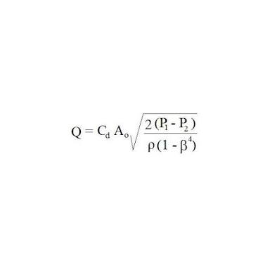
b. This equation allows calculation of pipe flow rate, Q, for measured pressure difference, P1-P2, known density of the fluid, Ƿ, the ratio of orifice diameter to pipe diameter, β, the cross-sectional area of the orifice, Ao, and orifice discharge coefficient, Cd.
1. Reduction of cross-section of the flowing stream in passing through orifice increases the velocity head at the expense of pressure head.
2. Reduction of pressure between taps is measured using manometer.
Complications:
a. Formation of vena contracta – Fluid stream separates from the downstream side of the orifice plate and forms a free-flowing jet in the downstream side.
b. Orifice coefficients are more empirial than those for the Venturi meter.
c. Orifice coefficient, generally, is 0.61 in case of flange taps and vena-contracta taps for NRe < 30,000.
d. In the process of calculating fluid velocity with a orifice meter, the velocity of approach is not included.
VELOCITY THROUGH AN ORIFICE METER
Uo =(Co / 1-β4)(2gc(Pa – Pb)/Ƿ)
Where,
Co – Orifice Coefficient
β – Ratio of CS areas of upstream to that of downstream
Pa – Pb - Pressure gradient across orifice meter.
Ƿ - Density of fluid.
Standard Pressure Tap Locations
 The three standard pressure tap configurations identified for orifice flow meters are as follows :
a. Corner Taps
b. Flange Taps
c. D – D/2 Taps
Conditioning Orifice Plate Advantages and Limitations
Common applications of orifice plates are those in which the process must follow standards and pretty much all clean, non-abrasive fluids such as steam, liquid, or gas.
Orifice Plate Benefits
a. Short straight pipe requirements
b. 2D up and down streams from most disturbances
c. Reliable
d. Easy Installation
Orifice Plate Limitations
a. Not part of industry standards
b. Edge Wear
c. High permanent pressure loss
d. Impulse piping with plate style version
Orifice Plate Common Applications
a. Limited straight pipe run
b. Offshore platforms
c. OEMs/ Skid Manufacturers
d. Retrofit poorly performing standard orifice plate installations due to limited straight pipe.
Under what conditions is an orifice meter preferred over a Venturi meter?
Advantages of Orifice Meter
⚫ Orifices are smaöl plates and easy to install/remove
⚫ Offer very little pressure drop of which 60% to 65% is recovered.
⚫ Orifice meter can be easily maintained
⚫ Measures a wide range of flow rates
⚫ They have a simple construction
⚫ They have easily fitted between flanges
⚫ They are most suitable for most gases and liquids
⚫ They are inexpensive
⚫ Price does not increase dramatically with size with
SIZING OF ORIFICE PLATE FLOW METER
⚫ Square root relation between flow and differential pressure for the orifice plates makes compromise in either flow or differential pressure inevitable in the sizing process
⚫ There are other sources of errors in orifice flow meter measurements
⚫ These include variations in pipe diameter, orifice plate machining tolerance and errors introduced due to flange taps
Orifice Plate Sizing Factors:
Some sizing factors greatly impact the accuracy of the orifice plate meter.
They are:
⚫ Differential pressure across the orifice plate
⚫ Maximum flow rate for the given application
⚫ Beta Ratio
b. Orifice coefficients are more empirial than those for the Venturi meter.
c. Orifice coefficient, generally, is 0.61 in case of flange taps and vena-contracta taps for NRe < 30,000.
d. In the process of calculating fluid velocity with a orifice meter, the velocity of approach is not included.
VELOCITY THROUGH AN ORIFICE METER
Uo =(Co / 1-β4)(2gc(Pa – Pb)/Ƿ)
Where,
Co – Orifice Coefficient
β – Ratio of CS areas of upstream to that of downstream
Pa – Pb - Pressure gradient across orifice meter.
Ƿ - Density of fluid.
Standard Pressure Tap Locations

a. Corner Taps
b. Flange Taps
c. D – D/2 Taps
Conditioning Orifice Plate Advantages and Limitations
Common applications of orifice plates are those in which the process must follow standards and pretty much all clean, non-abrasive fluids such as steam, liquid, or gas.
Orifice Plate Benefits
a. Short straight pipe requirements
b. 2D up and down streams from most disturbances
c. Reliable
d. Easy Installation
Orifice Plate Limitations
a. Not part of industry standards
b. Edge Wear
c. High permanent pressure loss
d. Impulse piping with plate style version
Orifice Plate Common Applications
a. Limited straight pipe run
b. Offshore platforms
c. OEMs/ Skid Manufacturers
d. Retrofit poorly performing standard orifice plate installations due to limited straight pipe.
Under what conditions is an orifice meter preferred over a Venturi meter?
Advantages of Orifice Meter
⚫ Orifices are smaöl plates and easy to install/remove
⚫ Offer very little pressure drop of which 60% to 65% is recovered.
⚫ Orifice meter can be easily maintained
⚫ Measures a wide range of flow rates
⚫ They have a simple construction
⚫ They have easily fitted between flanges
⚫ They are most suitable for most gases and liquids
⚫ They are inexpensive
⚫ Price does not increase dramatically with size with
SIZING OF ORIFICE PLATE FLOW METER
⚫ Square root relation between flow and differential pressure for the orifice plates makes compromise in either flow or differential pressure inevitable in the sizing process
⚫ There are other sources of errors in orifice flow meter measurements
⚫ These include variations in pipe diameter, orifice plate machining tolerance and errors introduced due to flange taps
Orifice Plate Sizing Factors:
Some sizing factors greatly impact the accuracy of the orifice plate meter.
They are:
⚫ Differential pressure across the orifice plate
⚫ Maximum flow rate for the given application
⚫ Beta Ratio
Comments